

22
2024
-
11
How to use the axle pin sensor
author:
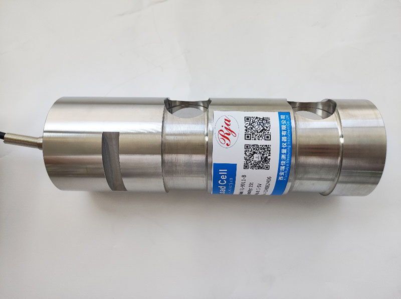
The pin sensor is a cylindrical body made of alloy steel or stainless steel
The axle pin sensor is widely used in our industry, and its use has also improved our work efficiency. Therefore, we need to have a certain understanding of the axle pin sensor. So, how is the axle pin sensor used?
The axle pin sensor is a cylindrical device made of alloy steel or stainless steel. It is a support area where two sensors and two load areas are supported by the pressure from the middle section. Strain measurement is achieved by a Wheatstone bridge sensor mounted on the pin to prevent adverse external influences (such as mechanical damage, dust, moisture, etc.). The output voltage signal from the pin sensor is generated, and the basic structure of the output analog and digital signals is based on the MV signal derived from it. The force input in the form of shear load occurs in the middle part of the shear load sensor, and when the sensors in the left and right parts of the support force sensor are changed, the resulting deformation is converted into an electrical signal proportional to the shear stress of the load. Considering the form of measurement, there is an optimal measurement direction for the pin sensor. In this preferred direction, the output signal can be maximized. In this case, the pressure sensor on the middle part and the main measurement direction in the same direction are indicated by two arrows on the sensor. The axle pin sensor is actually used in equipment and is also affected by temperature and transverse components. Therefore, our products have undergone temperature compensation and signal output compensation during production to ensure accuracy can be practically achieved on-site. There are two installation directions for the sensor: Horizontal installation: The sensor should be positioned under the rain cover (120 mm or deeper, below the outlet) at the air outlet, with the wiring conduit directly entering from the inside to the outside of the protective cover to prevent possible heavy impacts or the steel wire rope from automatically breaking. Vertical: The sensor installation should be designed at the top of the rainwater sensor's protective guard (more than 120 mm, depth of the side outlet), with the threaded wire directly leading from the internal protective cover to the pipeline, and a square design protective cover for the gate-type protective element (height 130 mm), loosening the rope back and forth to avoid friction damage to the protective cover.
Sensor,Machinery